LOS Software Insights
The Leicester Operating System (LOS) originated in the mid 1970s in the branch office of Business Computers Ltd. at 4 De Montfort Street, Leicester (more here).
Let's be clear! All the software on every Molecular 18 running LOS is handwritten in Machine Code and in nothing but Machine Code.
This does not mean that every detail is encoded on paper into Binary or Octal or (horror!) Hexadecimal, but it does mean that no use is made of any Assembler, Compiler or other artifacts, beyond assigning mnemonics to machine instructions and using the pre-printed layout of the coding sheet on foolscap paper.
There are several examples of completed LOS coding sheets scanned into PDF files on this website. Once you are accustomed to the discipline of writing programs this way for the M18 there is no need for an assembler. Reasons include:
- The simplicity of the instruction set: frequent encoding of instructions, backed up by the pocket reference card, soon commits much of it to memory.
- Page Addressing within each 1K-word memory boundary. Your code and data stays where you put it. When debugging, you know where to find, examine and even change it in memory. (On a machine with PC-relative addressing, whenever you edit your code reassembly is required and a debugging utility is needed to find it.)
- The adoption of Octal notation. An octal digit (0 to 7) is simply a convenient method of representing three binary digits. Thus six digits are sufficient to define the contents of a 17-bit M18 word. The format pp/ccss (where pp, cc and ss are page, column and step respectively each in 2-digit octal) is used for memory addresses due to the importance of the 1K-word page addressing boundary.
The major drawback of Machine Code programming is an inclination to use "patches" to extend existing code, either because it doesn't work correctly or to provide enhanced capability (or both). A JUMP is inserted to an extension placed elsewhere (because there is no room in-situ) which then jumps back to the original code or, unfortunately all too often, diverts to another patch, and so on. We've all done it as a quick fix, but it is never good practice. Sometimes a patch may fit in-situ (especially if there's space left in the original code), or be disguised as a subroutine.
Software Development Kit (SDK)
A typical Molecular 18 software development kit for LOS comprised:
- 0.5mm self propelling pencil (always sharp)
- supply of leads, HB hardness
- plastic eraser
- supply of blank Foolscap coding sheets
- correcting fluid and thinner for modifying photo-copied coding sheets
- Pocket Reference
- The first edition (October 1977) of the LOS Programmers’ Manual, supported by subsequent Bulletins as dated, aimed to provide application programmers and system designers with the essential information on the system’s capabilities as they became available. Development of LOS continued well into the 1980s and a much enhanced and revised edition of the manual was published in 1984.
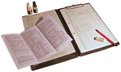
Programmers normally prepared their coding sheets at their desk. When you were ready to try out your code, you found an available terminal in the computer room and used the OP utility to load it in six-digit octal words. Beginners would first write all the octal machine code onto the coding sheets but after a little practice this became counter-productive except occasionally, when constructing subroutine control words for example. With just the two registers, page addressing, a modest instruction set and the adoption of octal notation everyone quickly became expert at assembling machine code on the fly at the terminal, especially as the OP utility echoed back the assembler decode as you typed.
No matter how carefully you checked your code, there was always a fair chance it would crash first time. So you always warned anyone else on the machine before you ran a test, waited two or three seconds so they could save their work to disc, then let it rip. Whilst your test ran you could use the OP utility to examine or indeed amend any memory location. Thanks to page addressing you could easily find your code and data and watch what was happening. If your test crashed you could inspect the debris through the control panel. Any subsequent amendments needed to coding sheets would be clearly marked with an asterisk in the margin, to be rubbed out after loading.
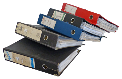 Completed coding sheets were stored in Foolscap Lever Arch files in Overlay Module sequence, with record layouts and any other overview information at the front. A complete set of documentation for one client could run to five hefty volumes, which we would carry with us on site visits.
Remote LOGON
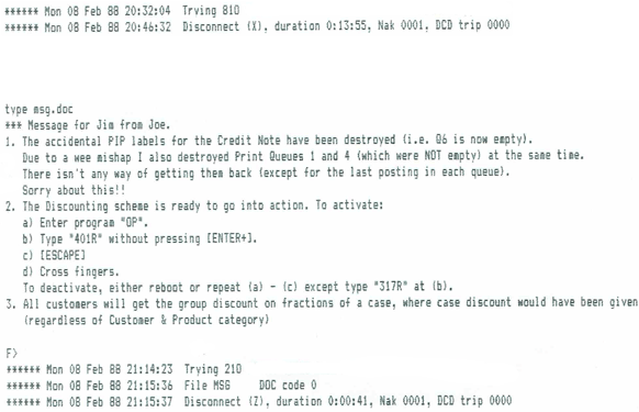
By the late 1980's I often worked remotely, logging-on to the Molecular through intermediate Epson QX10 computers at each end using (initially) a 300bps (V21) modem connection to load whole new programs directly onto users' live systems. The QX10s handled the telephone connection and the very necessary error handling through often noisy mechanical telephone exchanges.
LOGON would only be done by prior arrangement after everyone had gone home. When the time came to run the new code it could be a little nerve-racking knowing that any crash could not be dealt with until the next morning, though the outcome could be reported via a message sent to the remote QX10 log:
System Software
LOS includes a number of services for which there is no documentation because it was not expected they would be required outside of LOS itself and many were liable to frequent modification. To explore these services it is necessary to refer to the coding sheets (not entirely complete) backed up by a working machine (not known to exist but Kevin Murrell at TNMOC welcomes any information on the whereabouts of BCL equipment).
Some insights into the system software are given below.
Memory layout
The foundation of the Leicester Operating System is the "Firmware" created by BCL Brighton for the original Molecular Mark 1 mini-computer launched in 1971. The Firmware provides basic interrupt handling, device input/output support, fixed-point arithmetic and other key subroutines to support BCL's Sales Ledger, Bought Ledger and Payroll packages. A Mark 1 with 8K words of memory can run one such package at a time, with one keyboard (incorporating an 8 or 16 character display) and one printer.
The Firmware occupies pages 01, 02, 03 and 04 with pointers to its services in part of Zero Page and a 12-word bootstrap at 07/1600. This leaves most of Zero Page, pages 05, 06 and most of 07 available to the application packages. LOS incorporates the Firmware within its "Resident Library" (aka "Resident Services").
(This section is incomplete)
| From | To | |
|---|---|---|
| 0/0000 | 0/1777 | Zero Page. This page is directly addressable from all memory pages (so is shared by all Tasks).
|
| 1/0000 | 1/1777 | Page 01. Resident Library Routines.
|
| 2/0000 | 2/1777 | Page 02. Resident Library Routines.
|
| 3/0000 | 4/1777 | Page 03 and Page 04. Resident Library Routines and Interrupt Service Routines.
|
| 5/0000 | 6/1777 | Page 05 and Page 06. Task Partition 1. |
| 7/0000 | 7/1777 | Page 07. System list area and data area. |
| 10/0000 | 11/1777 | Page 10 and Page 11. Task Partition 2. Note: The address and instruction decode routines (used by OP and LIST utilities) reside in 10/0000 to 10/1377. Where programming work is to be carried out, it is preferable to avoid using this task partition if possible. |
| 12/0000 | 13/1777 | Page 12 and Page 13. Disc Transfer and handling and Task scheduler. |
| 14/0000 | 77/1777 | (when installed) Site use (Task Partitions, Shared Buffers, Resident Overlays, System workspace). |
Getmain
JSBR IZ 1704
Obtains a contiguous area of free system memory of size in words given by the contents of the A-register at entry.
On return, the A-Register contains the absolute address of the start of the area obtained. The contents of the B-Register are undefined.
The CPU HALTs at 03/1565 if a block of the requested size cannot be found.
LOS maintains a linked chain of free system memory blocks anchored at ZP/0037. The first word of each block points to the next until 000000 indicates end of chain and the second word contains the block size in words. This chain is established by the Initiator at 05/1034 from two manually maintained tables:
- 10/1600 lists all empty spaces within the first 12K of memory (i.e. the raw LOS) excluding that considered reserved for two 2K task partitions (at pages 05/0000 and 10/0000) and that considered reserved for resident overlays (3 sectors at 03/0000 if On-line Security is not required, 3 sectors at 07/1000).
- ZP/0416 of the installation's Configuration Table points to the list (within the Configuration Table) of all the additional memory available at that installation, i.e. that above address 13/1777 not required for task partitions, shared buffers or resident overlays. This table may include any space considered reserved at (1) above but not required for the reserved or any other purpose.
The Initiator uses Getmain extensively to obtain essential workspace for many system services, including file tables, file control blocks, outer print buffers and channel programs. Because channel programs contain executable code it is essential, when maintaining the above free memory tables, to ensure that no memory block spans a page boundary (therefore no block may exceed 1K words).
LOS does not provide a corresponding "Freemain" routine to release system memory. Although Getmain remains permanently available, once an installation is successfully initiated there is normally no further requirement for system memory. A BCL branch installation may be an exception, but it is assumed sufficient on-site expertise is available to deal with such a HALT.
Resident Overlays
Shared Buffers (aka Disk Caches)
The LOS implementation of Disc Caching, known within LOS as Shared Buffers because it predates the modern terminology, shares Shared Buffers in two ways:
- With all Tasks. When a file has a Shared Buffer, all that file's data transfers pass through that buffer exclusively.
- Optionally, by more than one file, to reduce the overall system memory requirement.
At an installation, all its shared buffers are manually defined in Column 07 of the Configuration Table, each definition requiring two words and known as a "Shared Buffer Control Block" (SBCB). The first word of the SBCB must be preset 000000 indicating empty and the second word must be the absolute address of the buffer. The Initiator copies Column 07 as found into its permanent location at 07/0700.
As LOS runs, the first word of each SBCB will hold the base sector number of the record currently in the buffer, allowing LOADQ to bypass read requests when that record is already in the buffer.
- In this situation LOADQ returns immediately if, and only if, this is a READ request, so no physical transfer takes place and the calling routine jumps the queue; otherwise the request is placed at the end of the relevant disc controller's queue and the calling routine resumes only when the transfer has successfully completed.
- LOS does not check that the record is on the same disk; it should, but it doesn't! If a buffer is shared by more than one file, it is left to installers to ensure they are on the same disk.
- LOS is not aware of the size of any shared buffer; it is left to installers to reserve sufficient space in system memory.
The System Control file is a special case of a file that requires a 3-sector shared buffer exclusively to itself at ZP/0400. This file has only one record, the System Control Record, which is fetched into the buffer by the Initiator, where it remains always accessible by all tasks via zero-page addressing. LOS provides the subroutine Stow System Control Record to write this record without the redundant requirement to LOCK it first.
File Handling Schema
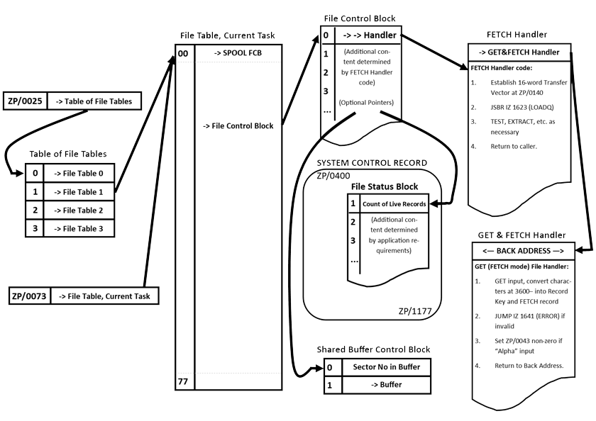
The File Table (pointed to by 00/0073) provides the active task with access to all the storage files required at an installation. Software designers assign a unique 8-bit File Identifier to each logical file (the capacity of the original 64-word File Table is extended to 256 files as described in LOS Bulletin No 23).
Because all the programs at an installation use the same File Identifier for each specific logical file (Spool File, Customer File, Product File etc.) the File Control Blocks (defining the attributes and storage location of the physical dataset) are established by the Initiator from information within the Configuration Table on bootstrapping. Individual programs do not, therefore, need to open (or close) files as they are already "pre-opened" by the system and remain so in the absence of any close/open facility.
The association between File Id and physical Dataset becomes much more flexible when there is a System Catalogue; in particular the catalogue maintenance and print utilities greatly simplify the reallocation of an installation's available disc storage in the light of operational experience.
Whilst the File Table's 256 file capacity amply satisfies the programming requirements at a user installation, program development at BCL's branch offices often involves staff working on different client test and/or demonstration systems on a single machine at the same time. The Table of File Tables (pointed to by 00/0025) enables an I/O Station to select from up to four pre-loaded File Tables via the Fn command, whilst the "LOAD" utility (new in October 1978) designates which File Table should be over-loaded into the Station's current resident File Table from the File of File Tables on the System Disc. Printer tasks automatically select the resident File Table of the task which posted their current job.
Note that a dataset is not required online unless and until a program attempts to access the data within it. In response to any disc transfer request LOS constructs a 16-word "Transfer Vector" at 00/0140 holding all the information required to execute the request and resume the calling task on its successful completion. If the request is to read data which is already "cached" in a Shared Buffer the calling task is resumed immediately. Otherwise the transfer vector is added to the end of the queue for the disc controller through which the relevant disc is mounted, or to the "unallocated" queue if the disc is not online.
The disc controllers give notice (by hardware interrupt) whenever a drive comes online or goes offline. LOS responds to an online notification by rescheduling any "unallocated" transfers that can now proceed, and to an offline notification by moving the relevant controller's transfer queue to the unallocated queue. LOS alerts users to any matters arising during transfer attempts and queued tasks remain blocked until their transfer is reported successfully completed (so there is no need for the calling program to check for itself).
LOADQ and the Transfer Vector
The File Handling Schema diagram makes reference to JSBR IZ 1623 (LOADQ) and the 16-word "Current DISCQ Transfer Vector" at ZP/0140 (which is permanently reserved system workspace).
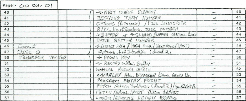
All disc transfers have to be placed into a queue to await execution. There is one queue for each installed disc controller, plus one "unallocated queue" for any transfers involving data not currently on-line. In LOS, LOADQ adds a new transfer to the end of the appropriate queue. If I recall correctly, this is the only way to queue a transfer except for for locked record updates which are always entered at the head of the appropriate queue.
Whilst transfer queues are awaiting execution they may be moved (maintaining the order of the entries) to a different controller or to/from the unallocated queue as cartridges go on/off-line. LOADQ returns to the caller only when the transfer is successfully completed.
Each entry, or vector to give it a fancy name indicative of its importance, in the queue is of fixed length of 16 words. The vector is created at ZP/0140 by the file handling routines prior to calling LOADQ and must contain all the information needed to resume the calling task when the transfer successfully completes. Hence there is a fair bit of room for two or even three levels of nested subroutine return addresses and all the other information (as, for example, when indexes need to be searched for the relevant data).
LOADQ is used by many parts of LOS. It's probably helpful to view it as an interface between two "layers" of logic. Although much of the Transfer Vector has a fixed format some of it is flexible (used for different purposes by different callers) as the needs of a Fetch Handler, for example, are somewhat different to those of the Spool Handler. The comments alongside the layout at ZP/0140 are more of an indication as to what you might find in each word rather than a guarantee (i.e. an aid to my memory at the time).
I/O Station Device Code Assignments
The CPU communicates with peripheral devices via I/O Instructions which operate on controllers on BCL-designed interface boards slotted into the bus in the CPU cabinet. Each controller is assigned a 6-bit Device Code, unique on the bus, via DIP-switches on the board. A cable connects the device to its interface board. Note that whilst a single disc controller may (in theory) serve up to four drives an I/O station requires two controllers as a keyboard functions independently of a display, even when integrated into a single unit.
On bootstrapping LOS the Initiator allocates device codes to I/O stations according to the following table:
| TASK No | Keyboard | Display |
|---|---|---|
| 01 | 50 | 40 |
| 02 | 51 | 41 |
| 03 | 52 | 42 |
| 04 | 53 | 43 |
| 05 | 54 | 44 |
| 06 | 55 | 45 |
| 07 | 56 | 46 |
| 10 | 57 | 47 |
| 11 | 20 | 60 |
| 12 | 21 | 61 |
| 13 | 22 | 62 |
| 14 | 23 | 63 |
| 15 | 24 | 64 |
| 16 | 25 | 65 |
| 17 | 26 | 66 |
| 20 | 01 | 11 |
| 21 | 02 | 12 |
| 22 | 03 | 13 |
| 23 | 04 | 14 |
| 24 | 05 | 15 |
| 25 | 06 | 16 |
| 26 | 07 | 17 |
| 27 | 74 | 76 |
| 30 | 75 | 77 |
The Initiator allocates Device Codes 30 to 33 to Line Printers, 34 to 37 to Serial (dot-matrix) Printers and 70 to 73 to Disc Controllers, 10, 27 and 67 are unassigned and 00 is avoided because ACK INT returns 00 when there is no I/O interrupt pendng. This seemingly haphazard sequence arises from redundant sequences formerly reserved for devices rendered obsolete by the arrival of the VDU Terminal.
Applications written for LOS generally assume I/O station displays are at least monochromatic 24-line by 80 column Visual Display Units. As the implementation of features such as cursor positioning vary between manufacturers it is best to use scroll mode. LOS endeavours to standardise the codes to clear the screen (ASCII CAN), beep the speaker (ASCII BEL), invert/revert the video (ASCII SO/SI) and map the integrated keyboard. All peripherals use 7-bit ASCII and (excepting Line Printers and Disc Drives with their specialist interfaces) serial data communication through the BCL 0314 Interface Board (CCITT V24 or EIA RS232).
Interrupts
Interrupt handling is a vital and fascinating aspect of computer technology. As a single CPU runs several orders of magnitude faster than any peripheral device connected to it, it is very capable of handling many independent processes seemingly simultaneously, i.e. multi-tasking.
As shown above, the M18 CPU communicates with connected devices via the I/O Instructions. An instructive primitive example (with interrupts disabled, as at power on or on pressing RESET) is the bootstrap (decoded at ZP/0100) where the CPU asks disc device 70 to read sector 0 of the exchangeable cartridge on device 0 into memory starting at address 0, then polls device 70's DONE flag continuously until the flag is raised indicating completion (not necessarily successfully). Note that disc controllers use hardware DMA (Direct Memory Access) to transfer the data between computer memory and disc without requiring the involvement of the CPU.
Continuous polling is acceptable in this instance because there is nothing else the CPU can do until it obtains more information (from the contents of the boot sector and the settings of the switch register) as to what is required and what facilities are available to it. As soon as the CPU turns its attention to other devices it becomes clear that polling each in turn is not satisfactory. The answer is to enable a device to request the CPU's attention only when it needs it, i.e. to interrupt the CPU when the device signals DONE.
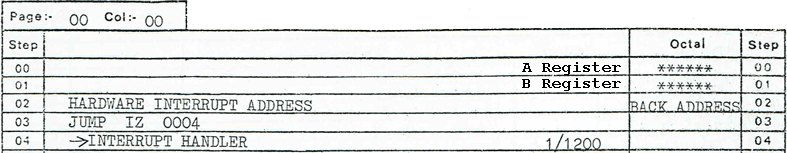
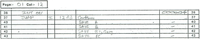
The M18 hardware implements an interrupt between instruction steps, effectively by inserting the two instructions INT OFF followed by JSBR Z 0002 (see flowchart). Thus an interrupt cannot be interrupted until re-enabled by software, which it should not do until ready to immediately dismiss the current interrupt.
LOS processes each interrupt sequentially as follows:
- Save the context (CPU registers and flags at interrupt)
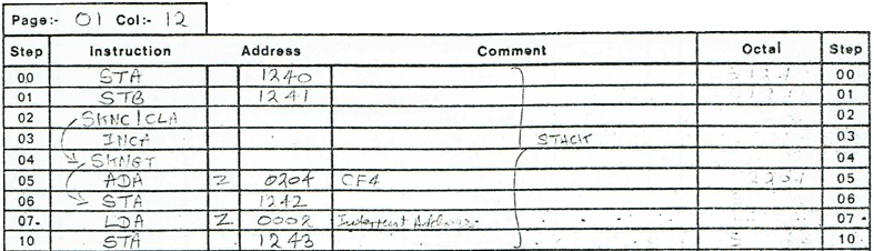
- Invoke the appropriate interrupt handler, on return from which
- Restore the saved context (excluding PC)
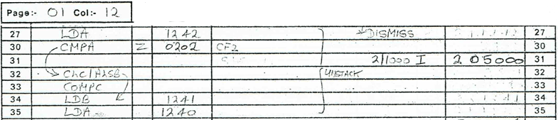
- Execute INT ON (hardware holds interrupts OFF until completion of the next following instruction) and immediately dismiss the interrupt by jumping to the saved PC address
Interrupt Priority
At any time more than one peripheral may be requesting CPU service, furthermore the CPU may encounter exceptional situations that are also best dealt with as an interrupt. At step 2 of the above list LOS first tests for the type of interrupt in descending priority order as follows:
| Priority | Name | Description | Address |
|---|---|---|---|
| 1 | MAINS OFF | See below. | 01/1211 |
| 2 | MA=SW | A debugging facility operated from the Control Panel. HALTs at ZP/0021. | 01/1217 |
| 3 | ACK INT | 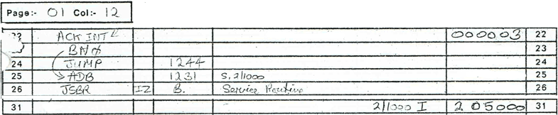 ACK INT loads the B Register with the Device Code of the highest priority peripheral requesting service, or returns 000000 if there is no such request. The M18 hardware prioritises peripheral interrupt requests by the relative positions of the peripherals' controllers on the I/O bus. | 01/1222 |
| 4 | MAINS ON | Immediately dismissed by LOS, i.e. JUMP IZ 0010 (disregarding the kludge at 01/1246) | 01/1244 |
| 5 | CONT INT | When activated at the Control Panel an interrupt is raised continuously (i.e. after every instruction step). LOS uses this facility to simulate Mains Off. | 01/1247 |
| 6 | PARITY | Raised on an attempt to access uninstalled memory. | 01/1252 |
The interrupt hardware described here dates from the original M18 Mark 1 released in 1971 and was retained in all later models except the Mark 2.
The Mark 2 hardware design sought, amongst other perceived advances, to significantly improve interrupt handling; see the M18 Mark 2 Hardware Reference (1973) which describes the Mark 2's Interrupt Stack at page 1:10.
The classic LOS application, telesales, relied upon LOS's exploitation of the essential simplicity of the Mark 1 hardware to provide unrestricted interaction between applications whilst the Mark 2 sought to isolate each application from any interference by cohabiting applications. LOS relied upon applications interacting cooperatively and provided services to assist, most particularly in the necessary sharing of printer resources and warehouse stock levels. The Mark 2 could not run LOS.
I/O Interrupt Service
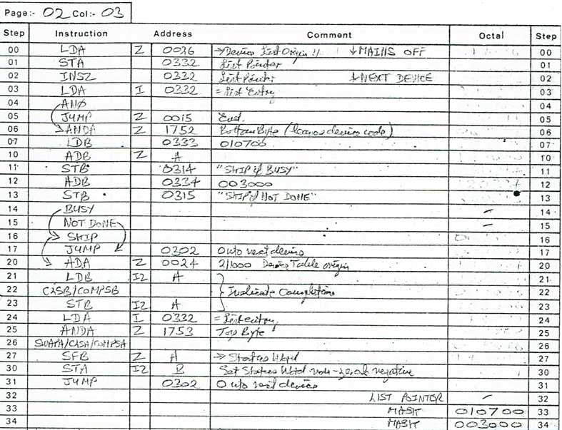
LOS holds a 64-word table at 02/1000, indexed by Device Code, of Service Routine addresses. On booting LOS each address is preset as 01/1266 (Service Unrecognised Device) until the Initiator replaces this with the address of the actual service routine for each installed device.
As the M18 can throw up an interrupt from a phantom device (among other quirks!) an appropriate default handler is necessary and forms an instructive example: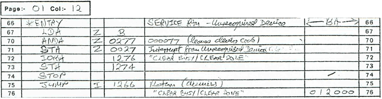
- As the above routine modifies itself by inserting the device code into the STOP instruction at 01/1274 it is not re-enterable but it is serially reusable and therefore safe to be shared by all unrecognised (phantom) devices as interrupts are OFF throughout its execution.
- All I/O interrupt service routines must clear the device's DONE flag as this turns off the interrupt request (CPU exception interrupts are cleared implicitly when the CPU tests for the exception). A service routine may either START (SET BUSY / CLEAR DONE) it's device (e.g. a keyboard, to await the next keystroke) or STOP (CLEAR BUSY / CLEAR DONE) it (e.g. a display output at end of message).
- A service routine cannot report directly to the outside world. In this example it sets a non-zero flag at ZP/0027 and leaves it to be picked up and processed by code running in a non-interrupt environment, in this instance by the Task Scheduler at 13/1143.
In the case of each I/O Station (usually a V24, i.e. 24 line x 80 character monochrome display with integrated keyboard) the Initiator establishes the keyboard service handler at 3752- and the display service handler at 3760- within the station's Task Control Area (the absolute addresses of these handlers are not yet inserted into the Device Service Table at 02/1000, this is undertaken at point of use by JSBR IZ 1621 STIN and JSBR IZ 1622 STOUT, being remnants of the Mark 1 Firmware):
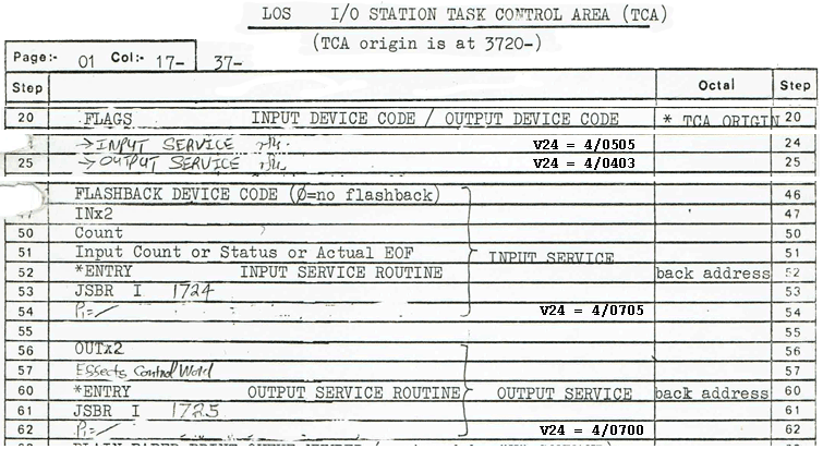
The above code is a nightmare to interpret! It seeks to allow a variety of terminals, each with their own keyboard layouts and display capabilities, to be used on the M18 without requiring application programs to be adapted to suit the terminal. Shareable serially reusable code for each terminal type is called to save on system memory requirements (most installations having a single terminal type).
Channel Programs (aka Device Drivers)
The concept of an interrupt service routine works fine with devices that only have one and the same thing to do at each interrupt, e.g. a character typed at a keyboard or output to a display, but gets tricky with anything more complex, e.g. printers and disc drives, that have many capabilities. A handler needs to keep track of what it is doing across interrupts and this traditionally involves setting and testing flags. It gets really messy handling disc interrupts this way especially when they go offline/online.
A far better concept is that of an I/O "channel program" (from IBM System 360 terminology), now generally known as a device driver. This concept turns the world inside out: whereas application programs are interrupted whilst the CPU serves a device, a channel program asks its device to do something and then waits, enabling the CPU to serve applications and other devices, until the device has done (or tried to do) what was asked of it. In LOS the interface between application program and channel program is just four steps long: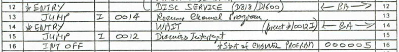
(illustrative example extracted from 06/1212)
- LOS uses the Channel Program / Driver concept for printers and disk drives. Template drivers are scattered around the raw LOS code for each supported device and may be found by referring to the "Service Generator Table" at 06/0401.
- Each template is written as if for Device Code 00 starting at offset 0000 of any page.
- For each such installed device controller the Initiator calls JSBR IZ 1704 GETMAIN to obtain empty system memory (outside any Task Partition) to create a unique driver from the template, relocating step offsets and inserting the actual Device Code as necessary (GETMAIN must never return a memory space that spans a page boundary!).
- The absolute address of the interrupt service handler (program step 12 in the above extract) is placed into the Device Table at 02/1000 at the Device Code offset.
- Applications access a device by starting its Channel Program (step 16 in the above extract). The Channel Program keeps on running after it has successfully completed the application's requested function, until it is overwritten by the next request from an application. This is crucial, e.g. in the case of disk drives where the channel program continuously monitors for online/offline status changes when there are no applications requiring the controller's attention.
A very elegant concept indeed!
Mains Fail
As was normal in the early 1970s, the M18 used non-volatile magnetic core memory, so it was not unreasonable to expect the system to pick up from where it left off in the event of any power off/on event. When semiconductor memory rendered magnetic core obsolete the M18 continued to meet this expectation with on-board battery backup. On the M18, CPU should signal a Mains Off interrupt with enough power left for a few hundred instructions.
A Mains Off/On sequence, unlike any other interrupt, includes a complete system reset. All Input/Output activity at Mains Off will be lost! To ensure that all tasks will resume with minimal data loss after power is restored the Mains Off handler takes the following action:
Replaces the instruction NOOP at the head of the Task Scheduler with JSBR IZ 0011.
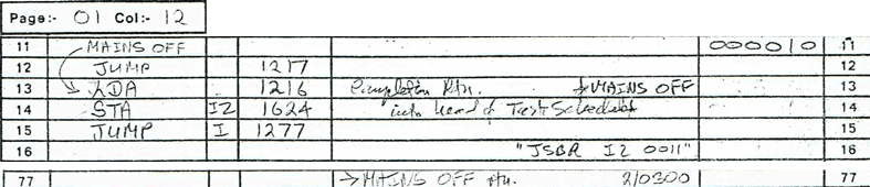
This instruction will call the so-called Completion Routine (described below) at the first entry to the Task Scheduler following Mains On.Tests for activity at each installed disk controller. Any controller found to be active (i.e. BUSY or DONE) is flagged as "Transfer completed but failed".
In the ordinary course of events any failed disc transfer is automatically retried.Places a JUMP IZ 0010 instruction (Dismiss Interrupt) at ZP/0002, issues an IO Reset instruction and HALTs the CPU at ZP/0021.
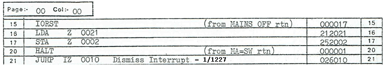
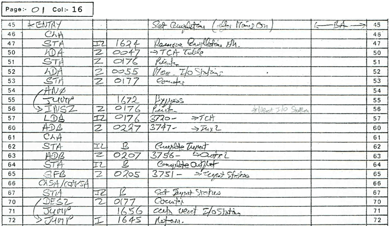
When the CPU runs from ZP/0002 following power on the Mains Off interrupt is dismissed. This will be promptly followed by a Mains On interrupt which is also dismissed. Soon enough thereafter the Task Scheduler will be entered and will call the Completion Routine (at 01/1645) inserted by the Mains Off handler. As the Completion Routine runs outside any Interrupt Handler there is no concern that it will run short of juice. The Completion Routine takes the following action:
Removes itself from the Task Scheduler by restoring the NOOP instruction at the head of the Task Scheduler.
For each installed I/O Station any output (PUT) in progress at Mains Off is flagged as "Completed OK", any input (GET) in progress is flagged as "Completed with error".
Returns control to the Task Scheduler.
As I/O stations spend most of their working lives awaiting input (i.e. in GET), they will beep "Error" after Mains On. Pressing the Error Acknowledge key will redisplay the prompt current at Mains Off, enabling the operator to re-enter their response and carry on.
Note that no specific action is taken in the event that a printer is printing at Mains Off. When this is the case, it is likely that all or part of a print line will be lost.
Very occasionally I encountered a machine which triggered Mains Fail too late (or not at all, the precise point could be adjusted by an engineer). LOS diverted the control panel's Continuous Interrupt switch to simulate a Mains Off: the machine halts at ZP/0021 and can then be powered off manually. At Mains On just press Continue if the keyswitch is not at Normal.
This recovery method is not part of the M18 Mark 1 Firmware; I must have been shown it by someone but unfortunately I do not recall when, where or by whom.
