General
Tasks
When LOS is initiated via the control panel switches, it creates core partitions for each task defined in the installation’s configuration table, and assigns a unique Task Number (from 1 upwards) to each I/O station and to each Printer. Each task is initiated at the start of the appropriate control program, and thereafter all tasks run asynchronously under the control of the Task Scheduler.
- The I/O station Control Program outputs the PROGRAM? prompt and, upon receipt of a valid reply, overlays the station’s core partition with the requested program and passes control to it. The program must return to the Control Program on completion (or on operator’s ESCAPE request) (by JUMP Z 1400 or JUMP Z 1402), whereupon the PROGRAM? prompt will be re-output.
- The Printer Control Program tests the Print Queue currently assigned to the printer for the presence of work postings. If work is found, the oldest posting is removed from the queue and assigned to the printer. The appropriate program is overlaid into the printer’s core partition unless it is already in the partition, and control is passed to it.
The program must return to the Control Program upon completion (by JUMP Z 1406 or JUMP Z 1402). If there is no work in the queue, the Control Program waits for postings to the queue and the printer is IDLE. The operators may, by command, change the print queue assignment at any time; the Control Program will switch to the new queue as soon as it receives such instructions.
Inter-Task Communication
I/O Station to Printer
For any application requiring printout, the I/O station task does not directly output to a printer; rather all output is written to the disc-held Spool File for later processing by a printer task. The format and content of these intermediate Spool records is defined by the application, except that each record is 124 words long (the last 4 words of the sector are reserved for system use: double-word program name and two chain-linking words).
As a general rule, the I/O station task should create compact spool records with the minimum of processing beyond input validation; wherever possible processing and updating should be carried out (at a lower priority level) by the printer task. This improves I/O station response time, reduces the spool storage requirement and eases the problems of recovery after a cancellation request or machine fault.
An application may require several spool records to define a printout (e.g. an invoice may be of any length), but usually a single record will suffice. The first record is referred to as the header record. When spooling is complete, the spooling task posts the header record number to a pre-selected print queue, normally determined by the type of paper required, and the system adds the posting to the end of the queue.
The system inserts the station’s task number into the first word of the Spool Buffer when an I/O station starts a new program, and after each SPOOL and each POST subroutine call (thus the receiving printer program may identify the station from which it has received work). Note: this provision does not reserve the first word of spool records.
Printer to I/O Station
The FLASH SINGLE STATION subroutine allows any task to send a message to a specific I/O Station. A printer may identify the Station from which it has received work by the task number in the first word of the spool buffer. If this task number is stored at 3742- (within the Printer’s Task Control Area) the system will flash the station pppp PRINTED BY x when the program returns to the control program (by JUMP Z 1406).
System to Operator
The general FLASH subroutine allows any task to send a message to all I/O Stations.
Operator to System
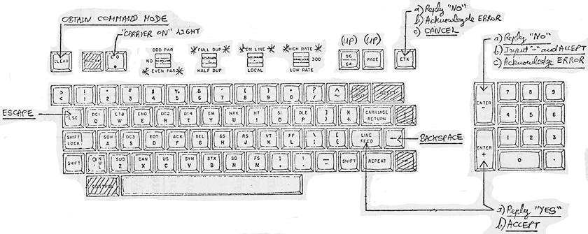
All I/O Stations are provided with a key which interrupts the current program and allows the operator to enter system commands. Available commands are listed in section 3 of this guide.
Operator to Operator
Program S is available to send a message to the screen of any or all I/O Stations.
Partition Map (2k Version)
Each task has its own core partition. All task partitions are of the same size and format (as defined in the Configuration Table). Because the partition maps are pre-defined and known throughout the system, there is a considerable saving in the number of parameters required by subroutines. Experience has shown a 2K partition size to be the optimum choice for Commercial applications, and all offsets quoted in this guide will refer only to a 2K partition, with a base offset of zero (i.e. first word of the partition is offset 0000-, last word is offset 3777-).
- The task OVERLAY AREA is 13 sectors long and occupies 0000- to 3177-. This will contain program code, data and work areas. Programs and Overlay Modules are loaded into the area by FETCH subroutine.
- The task MASTER BUFFER is one sector (128 words) long and occupies 3200- to 3377-. Used by FETCH, REWRITE and OVERWRITE subroutines as a one sector disc transfer buffer.
- The task SPOOL BUFFER is one sector (128 words) long and occupies 3400- to 3577-. Used by the SPOOL, UNSPOOL, POST, SPOOL & POST subroutines. A spooling task creates spool records here; an unspooling task receives spool records here (3577- contains the number of the next spool record in the chain). This buffer may be used as workspace (or as an extension to the Master Buffer) when spooling is not required.
- I/O STATIONS only: The task INPUT BUFFER is 128 characters long and starts at 3600-. Used by the GET and SPLIT subroutines and contains the most recent input from the station (ASCII format terminated by NUL byte).
- PRINTERS only: The task INNER PRINT BUFFER is 132 characters long and starts at 3600-. Used by the PRINT LINE subroutine, which always space-fills the buffer. The buffer holds one line of ASCII printout; a map of print positions against offsets is provided.
- The task CONTROL AREA occupies 3704- to 3777-. This is reserved for system use. The current program name (four ASCII characters) is held at 3716-.
Note Task Control Programs and Outer Print Buffers are within the system core space, not part of the task partition.
Programs And Overlay Modules
All Applications programs are held on disc as Overlay Modules. An overlay Module may be from 1 to 13 (decimal) sectors in length, and is identified by an Octal Number, range 001 to 400 (Module numbers 001 to 040 are reserved for Systems programs).
Currently, all overlay modules are contained on disc in the Overlay Module Library, assigned file identifier 02. An index to this library is also held on disc, stating the length of each module and the offset within the-task partition at which it is to be loaded.
A task may fetch overlay modules into its own core partition at any time (see FETCH Overlay Module subroutine), but in practice only the most complex of applications will overrun the 13 sectors available to the initial overlay. On the contrary, it may be found convenient and practical to group several related programs into the same overlay module.
Programs within LOS are identified by four character name (space filled if necessary) and type (I/O Station or Printer). A directory is held on disc giving, against each I/O station program name, the corresponding Module Number and logical Entry Point within the module. A similar directory exists for printer programs.
Overlay Modules are loaded and amended by the utility program OP. A systems utility program (PLM) is available to allocate disc space to a new overlay module, and to maintain the library index and program directories.
When an overlay module is fetched into core by program name, an option of the system may automatically resolve a block of offset addresses placed at the beginning of the module. (The library index contains flags indicating the modules to which the option applies.)
Direct Access
All tasks may transfer data to and from disc held files. Programs refer to files by a two-digit octal number, the File Identifier. Identifiers 00 to 10 are reserved for Systems Files, 11 to 77 for Applications Files.
The association between File Identifier and Data-Set on disc is, in principle, flexible. But as yet LOS does not provide file opening and closing facilities; therefore all files should be regarded as pre-opened by the system. This should be adequate where the machine is dedicated to the application.
Records within a Direct Access data set are identified by their relative record number; the first record number one. Records may be buffered several per sector (128 words), but records exceeding one sector cannot be contained within the task’s Master Buffer, which is the implied transfer buffer for the FETCH, REWRITE and OVERWRITE subroutines. The system provides automatic de-buffering and re-buffering facilities.
Disc Updates
The possibility of a simultaneous update of the same record (or, more precisely, the same sector) by two different tasks is eliminated within LOS because no mechanism is provided to write a record to disc without having first read that record and locked the entire disc transfer system. The lock must still be in force when the record is rewritten or overwritten.
Where it is necessary to prevent updating an entire file for a period of time this must be recognised and dealt with by the programs concerned.
The Bootstrap
To initiate LOS proceed as follows.
- Place any exchangeable disc (MASTER or SECURITY) holding a copy of the Operating System and holding the configuration Table appropriate to the installation onto Device 70 Drive 0.
- Insert key, turn to MANUAL.
- Press RESET. Wait for +15 volt light to come on.
- Load the five-word bootstrap at 000100:
004400
010670
010570
011470
020104
Note: This bootstrap is permanently core resident whilst LOS is running.
- Load MA and PC with 000100
- CLEAR THE SWITCHES.
- When the disc is READY, press CONTINUE. Turn key to NORMAL and remove.
Initiation takes approximately one second. Provided the disc holding the System Control Record and the disc holding the program library are on-line, all I/O stations will bleep and display PROGRAM?; otherwise all I/O stations will flash a message indicating which disc is required.
Recovery From Security
The above Bootstrap procedure should be carried out up to step 6 inclusive. The appropriate SECURITY disc must be placed on DEVICE 70 DRIVE 0; in the case of recovery of both FIXED and EXCHANGEABLE MASTER Discs this is the EXCHANGEABLE MASTER’s Security Disc.
After clearing the switches at step 6, raise switches 9 and 10. When the disc is READY, press CONTINUE and remove the key. Initiation will occur and copying proceeds automatically. The I/O stations will flash any requests for discs not on line. When copying is complete, all I/O stations will bleep and display PROGRAM?
Additional Facilities Of The Bootstrap
The control panel switch register acts as a function indicator to the initiator:
- ALL SWITCHES CLEAR
- Normal Start-up.
- SWITCH 9 UP
- Recovery from Security required.
- SWITCH 10 UP
- Initialize Device 70 Drive 0 Fixed Disc.
- SWITCH 11 UP
- Initialize Device 71 Drive 0 Fixed Disc.
- SWITCH 12 UP
- Initialize Device 72 Drive 0 Fixed Disc.
- SWITCH 13 UP
- Initialize Device 73 Drive 0 Fixed Disc.
Note: Switches 10-13 operate only in conjunction with switch 9 and only if all other switches are down. “Initialize” means label the disc as number 300 octal (i.e. system scratch disc). - SWITCH 7 UP
- Intercept required. The OS will be read into core; control then passes to the Systems Programming OP utility to enable Operating System and/or Configuration Table amendment.
- SWITCH 17 UP
- Intercept required. As for switch 7, except that switches 16-9 indicate the INPUT Device Code, 8-1 indicate the OUTPUT Device Code for the Systems Programming OP utility.
- SWITCH 16 UP
- Intercept for MK1 PACKAGE Amendments. The OS is read into Core and Control passes to the Systems Programming OP utility in such a manner as to use the utility to amend MK1 PACKAGE programs.
- SWITCH 6 UP
- Re-configure to single task. This facility is provided to overcome start-up problems caused when the physical configuration does not correspond to the configuration table held on the source disc (in particular, if there is insufficient core to match the requirements of the table, a parity halt (003356) will occur).
The facility amends the configuration table on UNIT 70 exchangeable cartridge to one I/O station and no printers (the single task is assigned core partition 5/0000). Initiation then proceeds as indicated by switches 17-7.
The I/O station is assumed to be an Alphanumeric Keyboard. If it is a 16-line VDU, raise switch 1. If it is a 24-line VDU, raise switch 2.
When the PROGRAM? prompt is obtained, program ACT may be entered to amend the configuration table to the full physical configuration.
LOS Bulletin No 8 (February 1978)
LOS may now be bootstrapped off DEVICE 70 FIXED. Method:
The first word of the bootstrap (at 000100) must be amended to read 004402.
This amendment must be made each time the system is to be bootstrapped off the fixed disc.
LOS Bulletin No 9 (April 1978)
LOS is available for the Molecular Mk I processor with D800 Discs. All applications software developed on Series III/1 and IV/1 is fully compatible except where MULTIPLE SHIFT or MULTIPLE ROTATE register instructions are used.
The bootstrap for the MK I processor is six words at 000100:
000017
000005
004400
010570
011470
020105
To start-up:
- Insert key, turn to MANUAL and raise STOP. If green RUN light fails to go out, power OFF and power ON.
- Raise switch 7 only (i.e. all other numbered switches down).
- Press START FROM SWITCHES.
- When UNIT 70 is READY, press INSTRUCTION STEP.
- CLEAR THE SWITCHES (or set required switch register mask).
- Press CONTINUE, remove key.
System Halts
The system may halt a task (by calling the HALT subroutine) for the reasons given below.
- BACK ADDRESS
- 001377
- Record Key Error. A-Register contains program back address. In the case of a Direct Access File, this means that the logical record number is outside the file limits.
- 001376
- REWRITE or OVERWRITE called out of context. A-Register contains program back address.
- 001375
- GET & FETCH File Type not supported. A-Register contains program back address (check that the File Identifier refers to a Direct Access File).
- 001374
- File Not Found. A-Register contains program back address. (File Identifier is invalid)
- 001373
- Hashfail on reading overlay module. A-Register contains program back address.
- 001372
- Print Queue not assigned. A-Register contains SPOOL back address. The-program must be corrected to assign a non-zero print queue to the task before calling SPOOL, by means of the SPECIFY I/O STATION PRINT QUEUE subroutine.
- 001371
- Print Program not found. The printer control program has been presented with a posting it cannot process because the program (named in the HALT message) is not entered in the Print Program Directory.
- 001370
- Non-privileged WRITE to Protected Sector.
Processor Halts & Loops
- PANEL LIGHTS
- 000021 HALT
- CONTINUOUS INTERRUPT if switch is down,
or MA=SW if switch is down,
or Mains fail.Raise switch if appropriate, press CONTINUE to dismiss interrupt.
Note: The CONTINUOUS INTERRUPT switch is programmed to call the mains-fail routine before halting the processor. - 000046→67 LOOP
- Disc status problems whilst bootstrapping OS. Program is continually retrying the disc transfer.
- 000104 LOOP
- Disc Status problem or Disc Not Ready whilst bootstrapping OS. To obtain status in A-Register, STOP and then load and INSTRUCTION STEP an 014370 instruction.
- 000153 HALT
- Hashfail on bootstrapping OS into core. Press CONTINUE to retry.
- 003333 HALT
- PARITY if light is lit, otherwise the processor has entered the interrupt handler with no interrupt pending.
Programmers’ note: This halt can be caused by a programming error. A PARITY halt will occur if an attempt is made to load from or store into a non-existant core location, whilst the interrupt handler may be entered inadvertently (e.g. by jumping into the A-Register). The A-Register will contain the address of the word following the instruction causing the interrupt. If CONTINUE is pressed, the interrupt is dismissed and processing resumes with unpredictable consequences. The system will attempt to flash the interrupt address to all stations.
- 007567 HALT
- Insufficient free core available. Examine A-Register to obtain GETMAIN subroutine back-address. If halt occurs during bootstrapping, the configuration must be modified to obatin successful bootstrap; otherwise press CONTINUE to resume (issuing task will be halted).
LOS 24-Line VDU
LOS Disc Layout
| Start Sector (octal) | Number of Sectors (decimal) | Description |
|---|---|---|
| 000000 | 1 | BOOTSTRAP |
| 000001 | 31 | not used (to avoid writing data on the vulnerable outermost track of early cartridges) |
| 000040 | 1 | DISC LABEL |
| 000041 | 1 | MASTER BOOTSTRAP (backup copy of Sector 000000 |
| 000042 | 3 | CONFIGURATION TABLE |
| 000045 | 3 | |
| 000050 | 95 | OPERATING SYSTEM (12K) |
| 000207 | Start of User Datasets | |
| 014537 | D818 cartridge max (6,496 sectors) | |
| 031277 | D1600 cartridge max (12,992 sectors) |
See also the recommended "System Disc" layout.
Configuration Table
Purpose:
To remove from the operating system, as far as practicable, installation and hardware dependent parameters. Thus the bootstrap will load the "raw" OS into core, then the initiator will read the 3 sector Configuration Table into 0/0400 and, by reference to the information in the table, convert the OS into a working version. The Configuration Table is then overlaid by the permanently core resident System Control Record.
Notes:
- The initiator copies 0/0600 to 0/0677 of the table to 0/1200 to 0/1277. This is intended to serve as File Table 0.
- The initiator copies 0/0700 to number of words stated in 0/0415 of the table to the address stated in 0/0414. This is intended to serve as an area for holding File Control Blocks. In particular the system FCBs should be placed here (i.e. Files 01 - 06 and 10).
- Elements in the File Table must point to the absolute core address of Word 0 of the corresponding File Control Block at its final position, not to its position in the Configuration Table.
- The initiator will FETCH into core (from File Table 0 Overlay Library) those overlays nominated in the Resident Overlay Table (pointed to by 0/0402). This table is of indefinite length - it is ended by a zero word. This facility is intended to allow users to write permanently core resident subroutines, etc, available to all tasks, without having to incorporate them into the raw operating system. Three sectors beginning at 3/0000 are available for this purpose.
Amendment Of Configuration Table
- Bootstrap as usual from 000100 but leave switch 7 up. One of the I/O stations will bleep and display OP?.
- Enter 1R to read the table into 0/0400.
- Amend the table as required, and escape back to OP?.
- Enter 1W to write the table to disc.
WARNING
The above amendment sequence updates the table held on the EXCHANGEABLE cartridge, Device 70, Drive 0 only. Where the fixed cartridge acts as a Master Disc, the amended configuration table must be copied to the Fixed cartridge (by restarting system and using program COPY; at NO OF SECTORS prompt, enter CT). DO NOT FORGET to carry out this step (otherwise security copies of the Fixed Cartridge will not hold the correct configuration table).
Note: This warning also applies to amendments to the Operating System. To copy the OS, at NO OF SECTORS prompt, enter OS.
Offset Addressing
The Molecular hardware implementation allows a program to run in any page of core (1K words beginning on a 1K boundary) provided it does not require indirect addressing (i.e. does not need to refer to locations outside that page or Zero page).
Indirect addresses must, however, be absolute addresses. Therefore, if a program requiring indirect addressing is to be run in any page without modification:
- Many (but not necessarily all) of its indirect addresses must be specified as offsets from a specified base point (normally the start of the first page of the program).
- These offsets must be resolved to absolute by software before access by Memory Reference Instructions.
LOS assigns each task a fixed 2K-core partition for its exclusive use. When programming it is convenient to specify addresses within the 2K partition as offsets from the beginning of the partition, address references outside the partition being specified as absolute.
An offset address is indicated on coding sheets by a "-" suffix (range 0000- to 3777-), and in core by Bit 17 set (range 200000 to 203777)
All the applications subroutines within LOS allow address parameters to be specified as Offset from the Partition Base or as Absolute, according as bit 17 of the parameter is or is not set, respectively. The RESOLVE OFFSET, RESOLVE OFFSET BLOCK, LOAD A FROM OFFSET, STORE A AT OFFSET subroutines are available to handle offset addresses within user programs. If offset pointers are blocked at the beginning of an Overlay Module an option of the system may resolve the block automatically when the Overlay is fetched from disc by program name (16 words reserved for this purpose should be ample).
Byte Addressing
1 Byte = 8 bits. A Molecular 17-bit word may hold 2 bytes; bits 16-9 are referred to as the Top byte, bits 8-1 as the Bottom byte.
ASCII characters are always held in bytes, one character per byte. Only 7 bits are required to define an ASCII character; the top bit of the byte is not used and therefore always zero in core. Bit 17 of a word containing ASCII is redundant and therefore always zero.
When passing character string addresses to subroutines, the parameter must indicate whether the string begins in the top or bottom byte. The convention is to set bit 16 of the parameter if the string starts in the bottom byte.
Notes
- Byte addressing imposes a 32K-word addressing limit on the string addressed. This may be overcome (subject to modification of LOS) provided all byte addresses over 32K words are specified as offsets.
- When processing character strings, it is expedient to convert the byte address to an “absolute byte number”. Example: to set up a certain print line comprising several 11 character numeric fields, it is desired to program a Binary to ASCII conversion loop. This loop involves incrementing P3 of the Convert Binary to ASCII subroutine call by 11 characters each time, and is best achieved as follows:
LDA    xxxx    P3 of call
LRA
ADA  Z 0213    CF11
RRA
STA    xxxx    P3 of call
Core Map
Minimum core requirement for LOS is 12K words; this includes two 2K task partitions (at 5/0000 and 10/0000).
Absolute Zero Page is directly addressable from all tasks and therefore contains common data and pointers, as mapped in the System Reference.
| From | To | |
|---|---|---|
| 0/0400 | 0/1177 | System Control Record |
| 1/0000 | 2/1777 | Library Routines, Command Handler. |
| 3/0000 | 3/0577 | Available for Systems Programming use. |
| 3/0600 | 4/1777 | Library Routines, Service Routines. |
| 5/0000 | 6/1777 | Task Partition 1 |
| 7/0000 | 7/1777 | System list area and data area. |
| 10/0000 | 11/1777 | Task Partition 2. Note: The address and instruction decode routines (used by OP and LIST utilities) reside in 10/0000 to 10/1377. Where programming work is to be carried out, it is preferable to avoid using this task partition if possible. |
| 12/0000 | 13/1777 | Disc Transfer and handling and Task scheduler. |
| 14/0000 | 37/1777 | Task Partitions and/or shared Buffer Areas. |
| 40/0000 | 77/1777 | Shared Buffer Areas, systems workspace. |
Standard Core Locations
- 0/0040
- = Currently scheduled Task Number
- 0/0077
- → System Date
- 0/0072
- → Task MASTER Buffer (3200-)
- 0/0067
- → Task SPOOL Buffer (3400-)
- 0/0066
- → Task INPUT or INNER PRINT Buffer (3600-)
- 0/0073
- → File Table
- 0/0074
- → Task Control Area origin (3720-)
- 0/0057
- = Maximum Plain Paper Print Queue Number
- 0/0060
- = Maximum (Deletions)( Print Queue Number
- 0/1300
- = Password 1 (General applications)
- 0/1305
- = Password 2 (Bought Ledger Package)
- 0/1312
- = Password 3
- 0/1317
- = Password 4
- 3714-
- = Printer Completion request word
B17=no cancel,
B16:B1=Task Number to be flashed at end - 0/0043
- After GET: = A-Register contents
- 0/0044
- After GET: → next Input Field in buffer
- 0/0045
- After GET: = Number of characters input
- 0/0151
- After FETCH: → Record (1st word) within buffer
- 0/0152
- After FETCH: = Logical Record Length (words)
- 0/0070
- Before SPOOL: → next Spool Record Number
- 3577-
- Before UNSPOOL: = next Spool Record Number in chain
- 0/0201
- MASK: B1
- 0/0202
- MASK: B2
- 0/0204
- MASK: B3
- 0/0210
- MASK: B4
- 0/0220
- MASK: B5
- 0/0240
- MASK: B6
- 0/0302
- MASK: B7
- 0/0316
- MASK: B8
- 0/0323
- MASK: B9
- 0/0332
- MASK: B10
- 0/0341
- MASK: B11
- 0/0344
- MASK: B12
- 0/0347
- MASK: B13
- 0/0352
- MASK: B14
- 0/0355
- MASK: B15
- 0/0356
- MASK: B16
- 0/0377
- MASK: B17
- 0/1752
- MASK: 000377 (bottom byte)
- 0/1753
- MASK: 177400 (top byte
- 0/0375
- MASK: 000177
- 0/0320
- MASK: 000300
- 0/0325
- MASK: 000500
- 0/0326
- MASK: 000600
- 0/0376
- MASK: 377777
- 0/0374
- MASK: 020040 (ASCII "SP SP")
DRI Printer Vertical Format Tapes
LOS Bulletin No 14 (April 1978)
The (five-track paper) tape provides two separate format “programs”, selected by the red switch on the paper feed unit (but remember when designing stationery that the paper depth must be the same on each program!).
On account of the slowness of line-feeding on the DRI (and on most other printers too), form feeds and vertical tabs are practically essential and a format tape will normally need to be designed for each type of stationery at an installation.

Manufacturer’s notes:
- By making use of one or all three of the idler pulleys, a wide range of tape lengths can be accommodated.
- The tape may contain several identical programs in sequence.
- The total number of lines of a tape should be an exact multiple of the number of lines on a form, in order to maintain synchronism between the tape and the forms.
- Tracks 2 and 5 contain start holes.
- Tracks 1 and 4 contain stop holes.
- A FF movement finishes at the line containing a start and a stop hole. This should coincide with the first line of print.
- A LF movement to a line with a start hole causes a VT movement to the next line with a stop hole.
- A VT movement ends at the next line with a stop hole.
- Tapes should end in five to ten lines perforated in every channel for splicing purposes. It is convenient to treat the beginning of the tape in a similar manner to define the first line of the program and subsequently to trim to the beginning.
- When splicing, trim the corners. Use flexible waterproof adhesive, and ensure that the leading edge is underneath, to prevent its being pulled up by the brushes. Check that all holes are free of adhesive.
Since the printer will accept eight-track tape, format loops may be mass-produced if a paper tape punch attachment is available. A “stand-alone” utility is available within LOS for this purpose as follows:
| Step | Action |
|---|---|
| 1 | Bootstrap as usual but leave SWITCH 7 UP when CONTINUE is pressed. |
| 2 | Set the switches to the number of loops to be punched. |
| 3 | STANDARD 66-line loops: At the station which displays OP?, enter 6/0200H. The required number of loops will be punched at punch device code 33 (station returns to OP?). |
| BLANK 66-line loop (i.e. Tracks 3 and 8 only punched on all 66 lines): Enter 6/0220H. | |
USER-DESIGNED loops:
|
